Here you will find more information that will help you understand how system works, and how you can use this solution in your factory.
Technical specifications
| Name | Value | Description |
|---|---|---|
| Digital inputs | 4 | 0-40v, 6-9v threshold |
| Power supply | 12-36v | DC |
| Power consumption | 1.5-2w | Without light tower |
| Light tower outputs | 4 | fixed 10v 100ma output for each channel. Used to drive LED Light tower. Can drive external 12v relays and can be used for additional control. |
| Outputs | 2 | (Optional) One high speed open collector transistor output., one relay output |
Peripheral signals
Input and output data signals.
Signal sources
Zetascout device supports binary and data stream input sources:
| Purpose | Count | Description |
|---|---|---|
| Optocoupled digital inputs | 4 | Voltage level: DC 0-45v, 6-9v treshhold; Maximum frequency: 1khz at duty cycle 40-60%; |
| Front panel button | 1 | Front panel button |
| RS-485 serial interface | 1 | basic MODBUS or RAW data support |
| Bar/QR code reader | 1 | CMOS 2mipx camera reader in autoscan mode with red laser mark. Supported formats: 1D:UPC-A/UPC-E;EAN-8/EAN-13;Code128;Code39;Code93;Code32;Code11;Codabar;Plessey;MSI;Interleaved 2 of 5;IATA 2 of 5;Matrix 2 of 5;Straight 2 of 5;Pharmacode;RSS-14;RSS-14 Expanded;RSS-14 Limited;Composite Code-A;Composite Code-B;Composite Code-C; 2D:PDF417;Micro PDF417;Data Matrix;QRcode;Micro QR;Aztec;MaxiCode |
| External USB Bar/QR code reader | 1 or 2 | (Optional) and only in cufiguration with 2mpix CMOS video camera. |
| Internal RFid reader | 1 | (Optional) 13.56Mhz MIFARE or 125khz unencrypted ASK RFid cards |
| External RFid reder | 1 | 3-rd party external RFid reader using Wiegand protocol can be connected. In this case any encrypted keys can be used. Please note: consuming 2 digital inputs (in2 and in3) |
| IEEE 802.15.4 | 1 | (Optional) Wireless protocol to connect external data sources |
| CAN-FD | 1 | (Optional) RAW CAN-FD protocol |
| USB2.0 | 1 or 2 | (Optional) and only in cufiguration with 2mpix CMOS video camera. |
| 2Mpix CMOS video camera | 1 | (Optional) Front mounted video camera for workplace visual monitoring. Please ask for available FOV angle. |
Peripheral control
Devices can be controlled by zetaScout system
| Purpose | Count | Description |
|---|---|---|
| Label printer | 1 | USB or network connected label printer. Customized labels using LUA scripting language. |
| Light tower | 1 | Four constant colors, (red, green blue, yellow) light tower dedicated to display workplace status. |
| Relay output | 1 | (Optional) |
| Transistor output | 1 | (Optional) High speed open collector transistor output. |
Data formats
All data are collected and stored in internal ZetaScout device memory and can be exported in CSV, HTML, JSON, XML formats. ZetaScout device can push data directly to almost any database server, or can send data using your API.
RAW data output
Data fragment in simple RAW format how it stored in device memory, explained below.
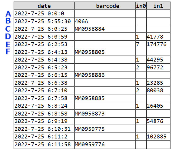
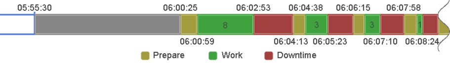
|
RAW data output in HTML table format (B) Employee ID at work place registered. (Worker at workplace 05:55:30) Time interval from (B) to (C): workplace setup time. (4min 55sec) (C) Task bar-code read (First task begin) (work starts at 06:00:25) From (C) to (D) equipment for task Preparation/setup time (36sec) (D) First equipment/worker action detected. ( after programmable timeout of new task in0 column value always 1) Please read [Downtime explained] below for downtime calculation algorithm. (E) To complete whole task worked made 1+7=8 work cycles, Work time (1min 54sec) From (E) to (F) time interval registered as Downtime (1min 20sec) (F) Next task begin, Preparation/setup time Jump to (C) Notes:
* This data also can be used to measure tool wear or to calculate scheduled maintenance. |
 |
 |
|
Downtime explained
Maximum *takt time can be set for each workplace idividually. For example we set takt time to 30 seconds in zetaScout device configuration.
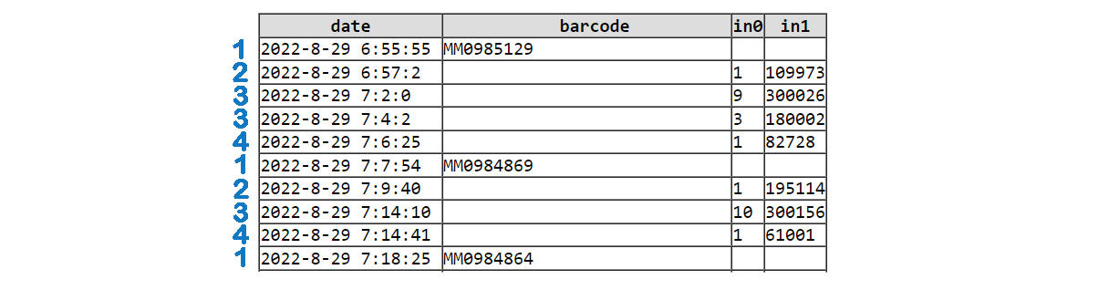
Steps:
1. Task barcode scan (STATUS prepare)
Interval from [1] to [2] is prepare time
2. First action detected, equipment prepared and task begin (STATUS work)
3. in0 data greater than 1, this means groups of events counted without going to downtime and delay betwwen takt event does not exceed workplace programmed downtime.
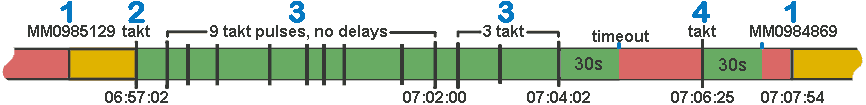
Record timestamp is exact moment of last takt pulse in this group of takt's
Interval from the end of [3] to [4] minus programmed timeout are calculated as downtime because there no action in longer than 30 seconds programmed period. (STATUS downtime)
4. in0 record value is 1 indicate thet process state returned from downtime to work .(detected first event after timeout) (STATUS work)
time interval betwwen [4]. and [1] minus programmed timeout are also calculated as downtime. (STATUS downtime)
*takt: Takt time is the rate at which you need to complete a product in order to meet customer demand. Takt time was first used by German engineers during the 1930s, later this concept started to be used in Japan. Toyota used it as part of the Lean principles.
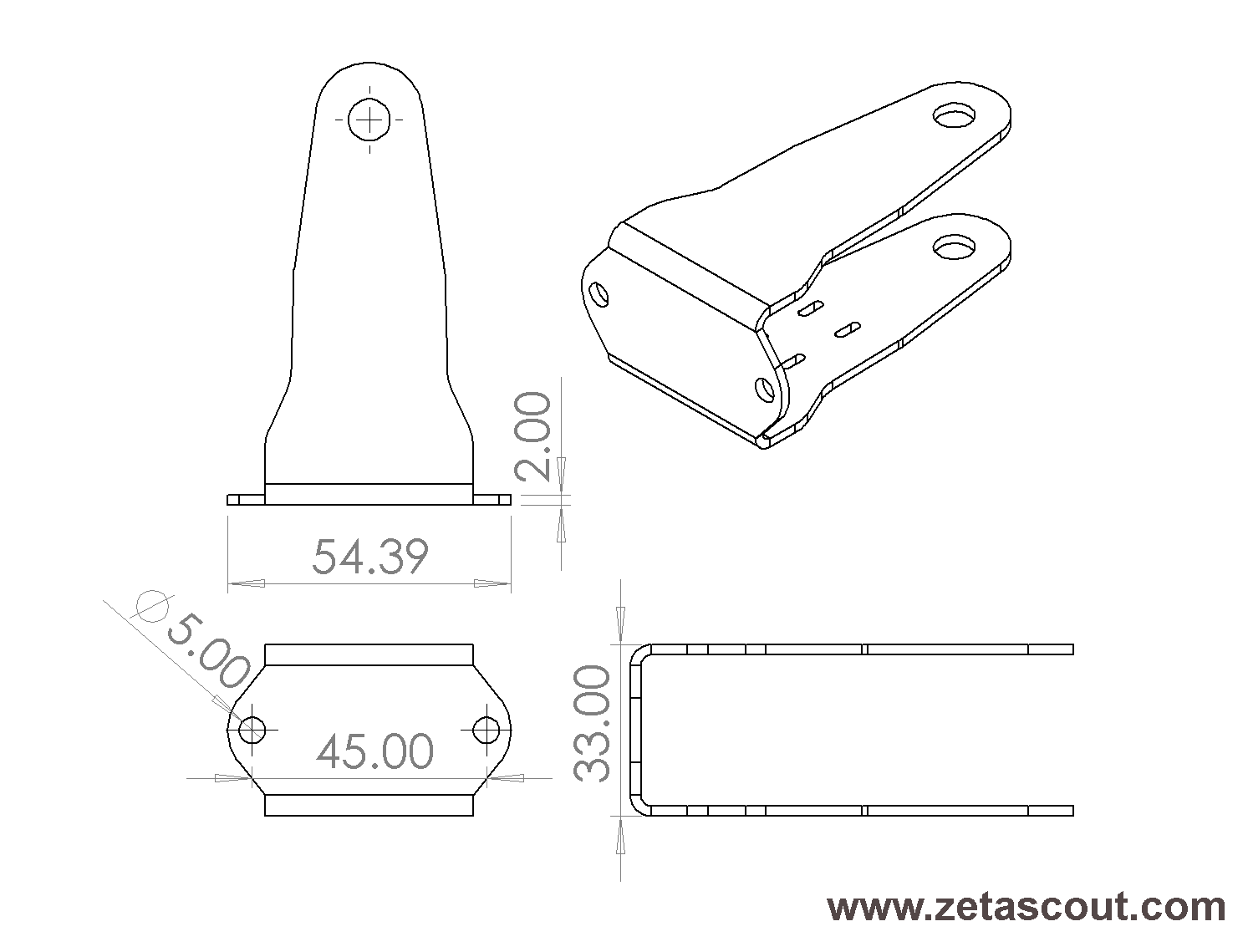
Mechanical information
zetaScout workplace activity monitoring device made from ABS plastic and are avialable in 3 colors: Black, light Gray and White (rare used). Two versions of light towers are available: build-in, and external.
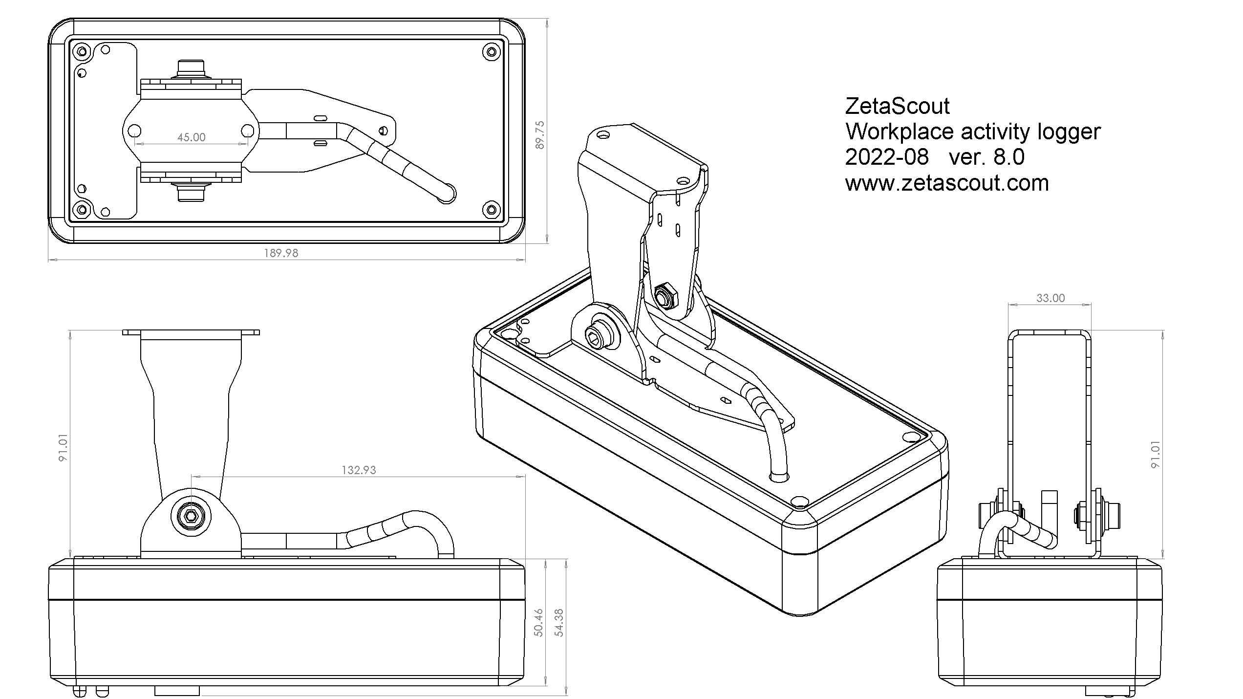
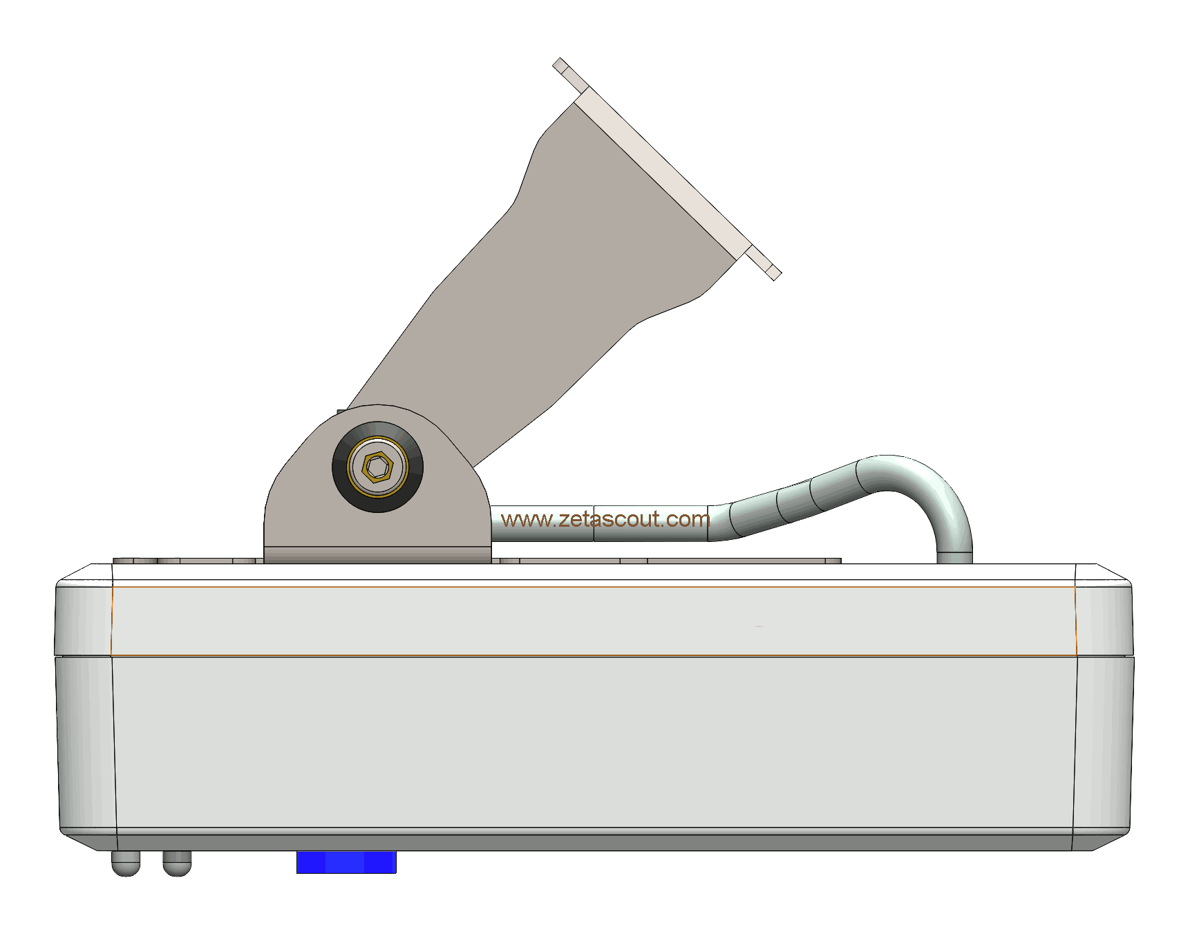
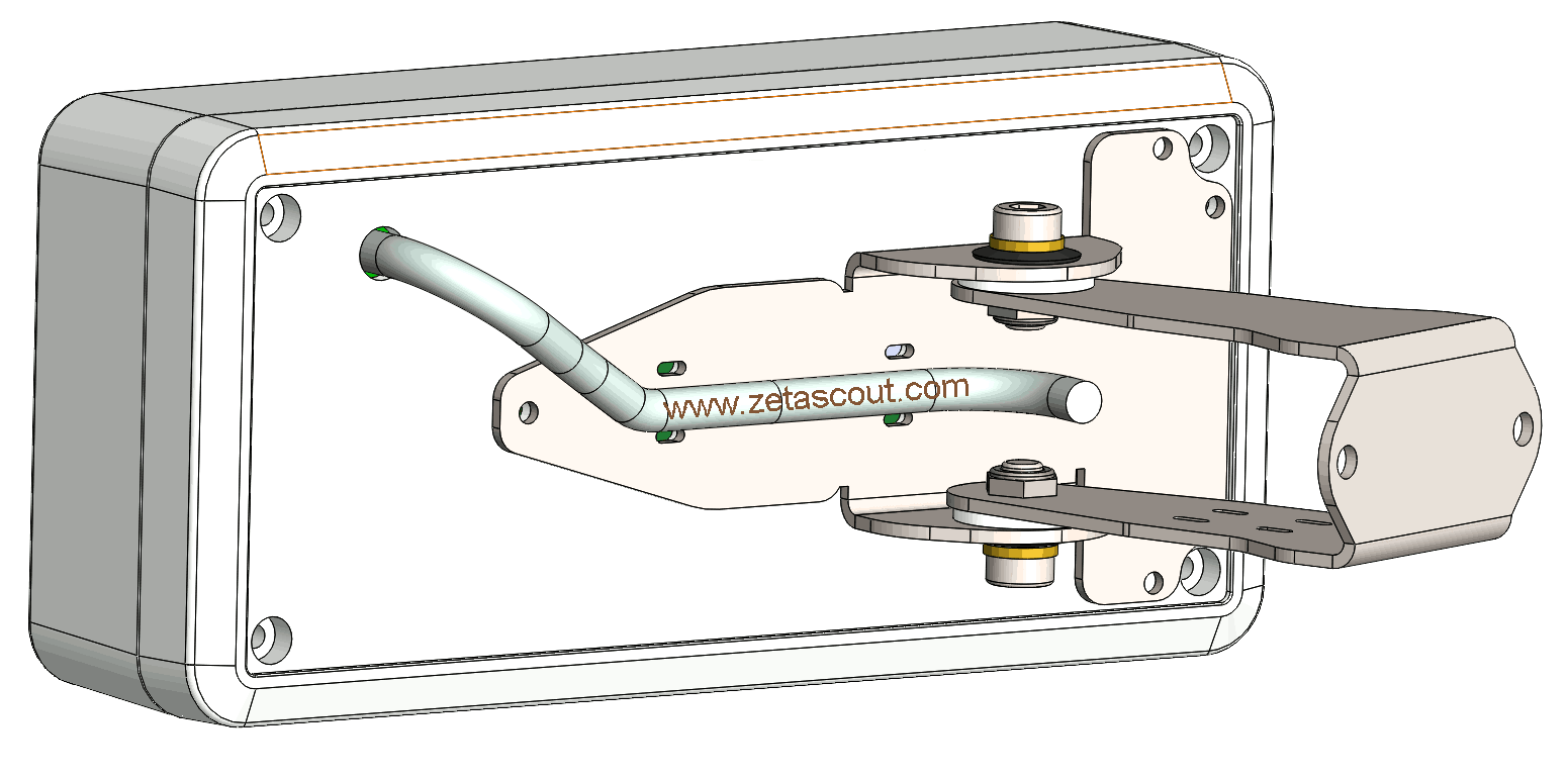
ZetaScout mounting
Installation of the device at the workplace is very important. The employee must be comfortable using the device, this will save time and make work more efficient. In many cases, our customers ask for the ability to easy way rotate, twist and move the device to comfortable position, in this case we pay a lot of attention to make the installation as simple as possible.
Mount option using Holder-2 and Holder-2D mounting elements
img-carousel-mount-h2d2d
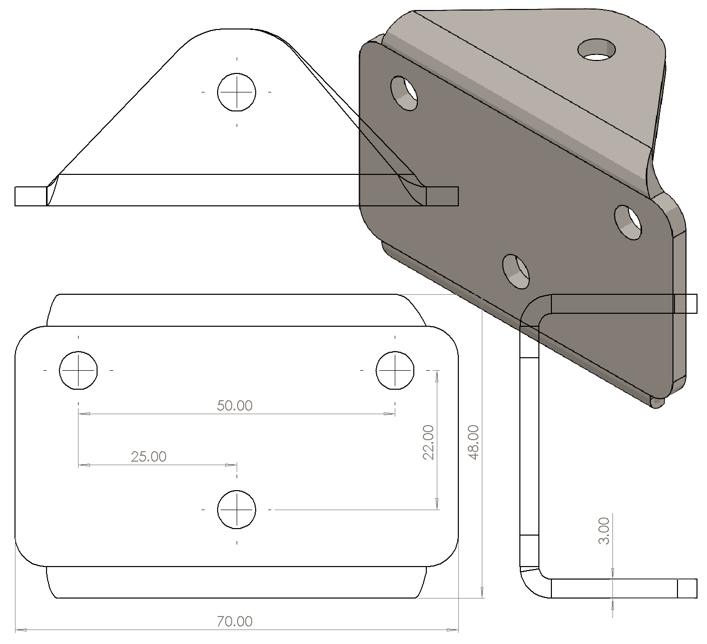
Mount option using Holder-2 and Holder-D and Holder-40x20x200mm mounting elements
img-carousel-mount-h2d2d40x20
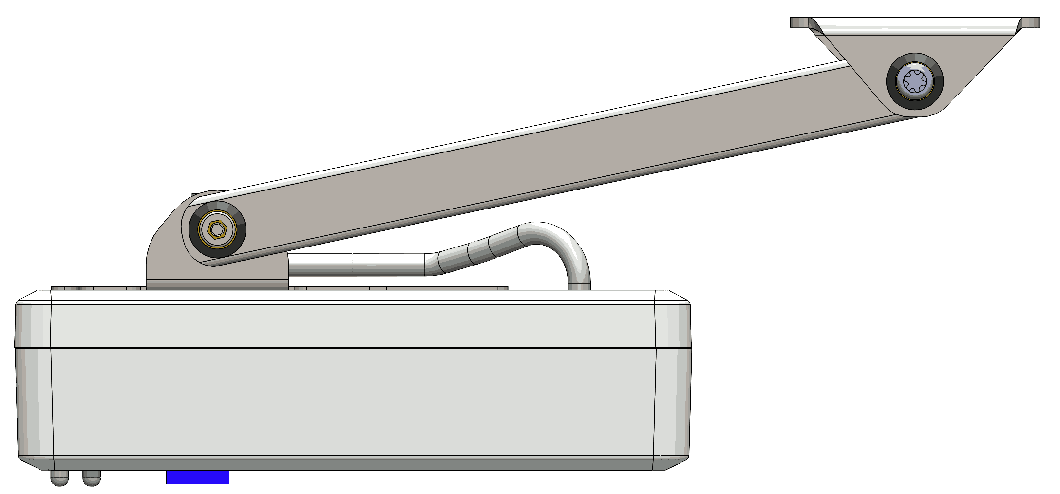
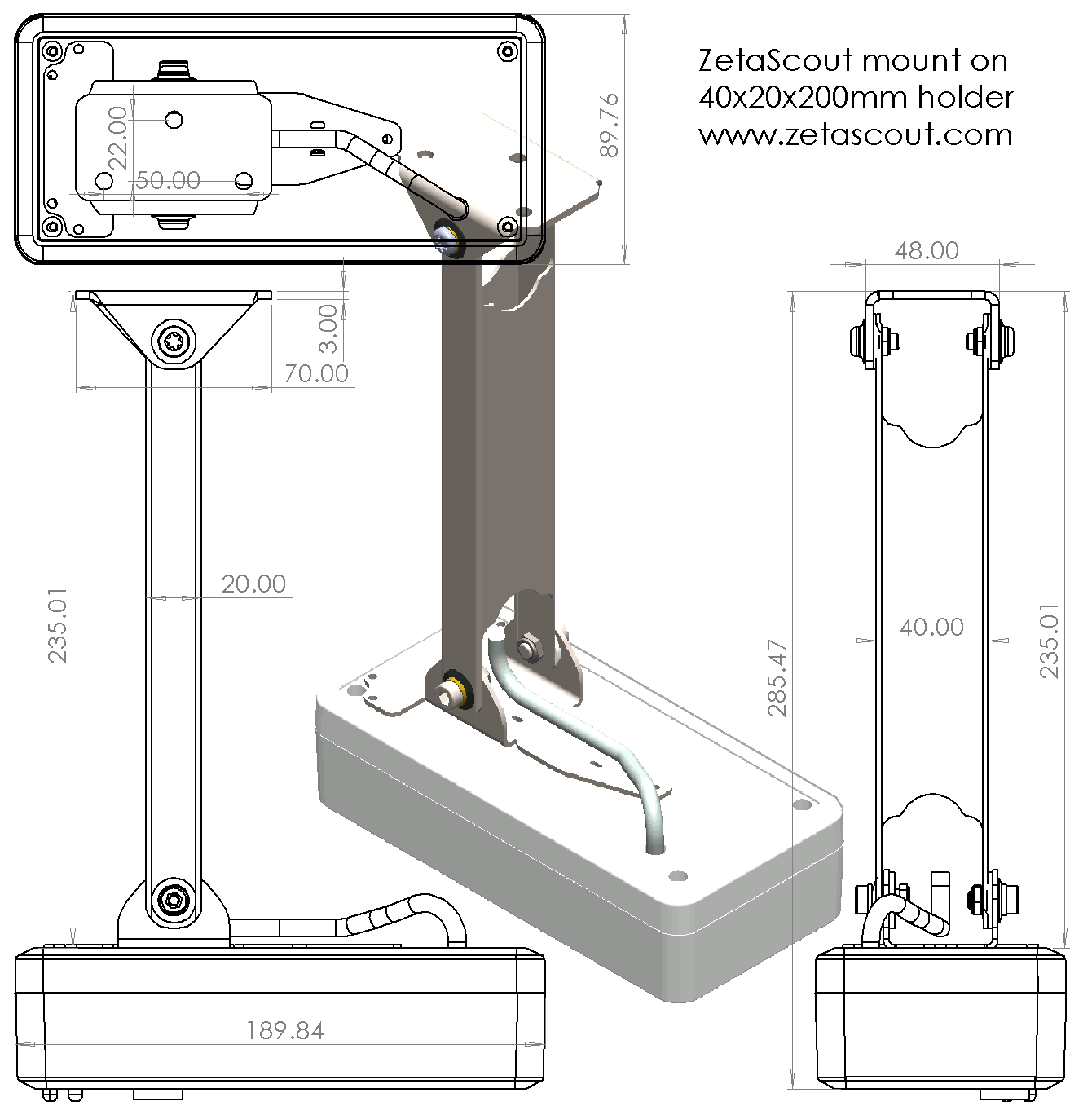
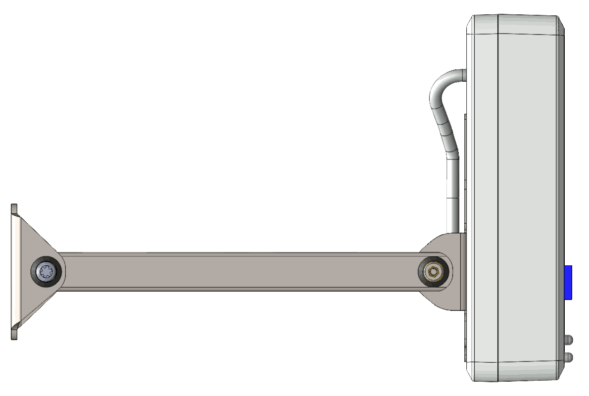
Distance from wall to device back panel 235mm. Also 335mm and 435mm options available.